- Exterior & styling
- Be the first to comment!
- Read 7338 times
Electric mirrors
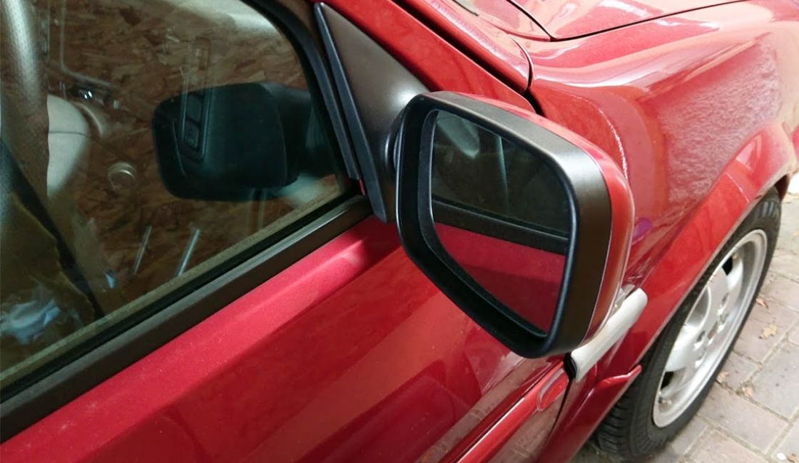
Rover Metro/100 Electric & Heated Mirror upgrade. This Guide is suitable for all Mk3 Metro's and Mk4 Rover 100's.
Parts required
- A pair of MGF, MG TF or Rover 200 96 to 99 electric door mirrors
- Electric mirror adjustment switch
- Wires and relevant connectors.
- Optional Rover 400/ Honda Civic Heated Mirror Switch (Metro one if unobtainable) if heated mirrors are not to be permanently on.
Tools required
- Power File
- Angle Grinder
- Small flat model file
- Digital multimeter
- Soldering Iron
- Wire cutters
- Tape ruler
- Electrical Pliers
- Small jewellers screwdriver
- Pozi drive screwdriver
- Small socket set – ¼ drive
- Stanley knife
- Small flat file
- Haynes manual for removal / re-fitting information
- Solder
- Primer
This procedure gives the details for fitting the R200/R25 switch. For fitment of the R400/R45 switch please view the Rover 400 bezel information near the end of the guide. In the MG and R200/25 the heaters are permanently wired on. This function is optional to switch the heaters on/off. Three types of switch can be used:-
- A modified Metro H.R.W. (heated rear window) switch can be used
- The Rover 400/R45 H.R.W. switch.
- Standard rocker switch
Making the wiring harness
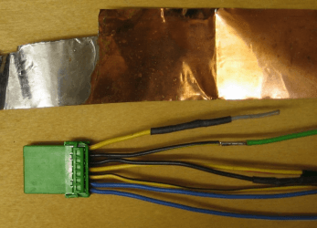
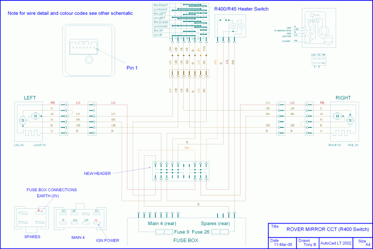
Study the schematic and physical layout to build the harness. All information for items required, the wire to be used and connectors etc is given on those drawings. See photographs for details of connectors and finished harness.
- With respect to wire colour codes, this is totally arbitrary. Use the colours listed or choose your own colours.
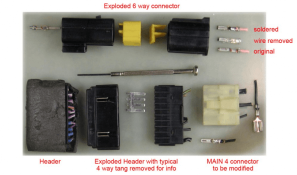
- To dismantle the 6 way sockets and plugs, use the jeweler's screwdriver. Firstly remove the yellow alignment cover. There is a small tang inside which has to be lifted to remove the pin.
- The header is the same. Prize apart and then use jeweler's screwdriver to remove pins. Re-arrange tags as per the schematic.
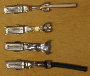
- To reuse the pins carefully use the angle grinder to grind the crimp away to release the old wire. A file can be used to do this but it takes ages so use the angle grinder. The three stages of how to prepare the pins is shown in the Connectors photograph.
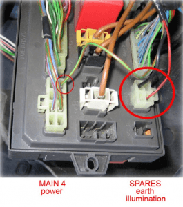
- Using the Stanley knife and file, cut the obtained MAIN 4 connector to fit into the SPARES fuse box socket.
- Click Here to view wiring diagram for Rover style switch
Door mirror apertures
This is optional. But it is felt that this should be done so that the wires do not have a tight bend over the metal.
Where the mirror is screwed in place, the metal in the middle has to be removed to accommodate the new wires from the mirror. Follow Haynes manual to remove the existing mirror assembly and its associated plastic cover inside the car. Then, with the angle grinder and power file remove this metal. Finally treat bare metal areas with primer paint. See photograph for finished aperture.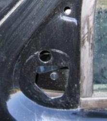
Initial test
- Disconnect +ve from Battery.
- Remove the fuse box cover and drop the fuse box down – two bolts – one each side.
- Temporarily connect everything up.
- Re-connect +ve to Battery.
- The mirror power is supplied from the ignition cct. so for this functional test the ignition has to be switched on.
- Test mirrors for correct operation. Check heaters – mirrors should start to feel warm.
- If all ok then continue. Disconnect everything ready to install in car. If not fix problem!
Fitting the mirrors
- Following the Haynes manual, remove all door trim and door card. In area below mirror carefully peel back the door membrane (try not to tear).
- To fit the new mirrors temporarily remove the connector shell so wires are small enough to fit through the existing hole for the manual rod adjustment, If not, widen the hole, so that wires can be fed inside the door.
- Remove interior mirror manual adjuster if fitted and prize the triangle shaped interior trim from the top to gain access to two Phillips screws which hold the mirror on.
- Undo these and hold mirror to prevent it falling and remove. Keep Metro/ 100 mirror base on the outside of door and fit new electric mirror.
- Make sure connector is feed down between the 2 skins of the door.
- Screw in new mirror and refit the connector shell.
- On the inside of the door fit the new blanking plate.
Fitting the harnesses
- Disconnect +ve from Battery.
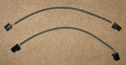
- Fitting the door harness is straightforward, a completed harness ready for fitting is shown below:

- Temporarily remove connector shell that goes inside car, wrap the end of the mirror wires with masking tape then feed this through the existing door harness aperture, rubber tube etc into the car.
- When harness is through re-fit connector shell.
- Fitting the main mirror harness is awkward. A completed harness is shown below:

- Referring to the Haynes manual, remove the radio and glove box
- To do it correctly it should follow the vehicle harness behind the dashboard. The worst point is feeding the harness between the existing car harness and windscreen vent to the right of the radio aperture. Best to temporarily remove the connector shell (cover wires in masking tape) for the passenger side and then feed harness up via driver’s foot well. Access is very limited here but can be done.
- When harness in place fix to main vehicle harness with tie wraps.
- For reference see photos of the harness fitted with the dashboard removed below.

This is the problem area behind the dashboard – but the harness can be threaded through this small aperture from the driver’s foot well. If the passenger door mirror connector is temporarily removed and wires covered in masking tape it will thread through. As can be seen this harness was fitted with the dashboard removed. - Connect up mirrors to door harnesses and then those to main mirror harness. Finally connect main mirror harness to fuse box.
Fitting the mirror and heater switches (Rover 200/ Rover 25 & MGF Switch)
- The above picture shows the Rover style switch fitted to the right of the steering column. It also has the standard Metro/100 electronically adjustable headlamp switch and a aftermarket rocker switch to operate the heat mirror elements.
- To fit the switch cut a square hole in the plastic using the Stanley knife.
- When removing Switch from donor car, record width and height of the hole and replicate it.
- Note - use smaller hole to start with and work upwards with trail and error. This will avoid cutting to much and the switch not holding to the dash.
Alternatively if you can find a Mk2 Metro heater blanking plate (although this is very rare) you can mount the switch onto that to avoid cutting into the dash itself
Final test
- Re-connect +ve to Battery.
- Now carry out another functional test before refitting everything else back into place.
- If all ok then refit glove box, radio, fuse box, fuse box cover, door furnishing etc.
The mirror switches
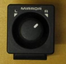
Rover 200 & 25 style switch
 |  |  |
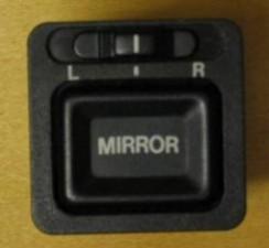
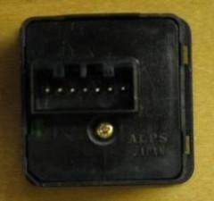
Rover 400 & 45 style switch
 |  |
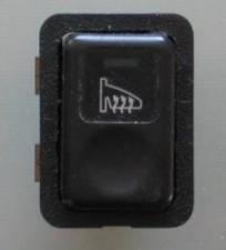
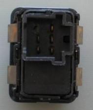
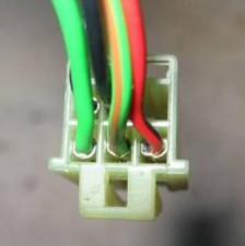
Rover 400 & 45 heated mirror switch
 |  |  |
Mirror detail
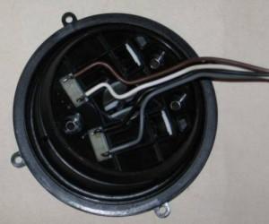
Picture of the two actuators with the wires attached to them.
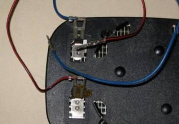
Picture of the heated mirror with the two heater wires.
Harness Connectors, information on wiring, pins etc.
Picture of the different types of connectors to be used (click to enlarge)
Note: the header shown is not one from the fascia but a generic one from the main harness. They all look the same but have different tang configurations
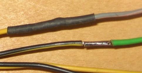
Here is some detail of the wiring and pins. The connector shown is for the R400/R45 switch. This one is not very easy to dismantle; so detailed is the solder splice. With respect to the wires the insulation is cut back by approx 5mm then tinned. A piece of copper foil, cut to size and previously tinned is wrapped around the two ends of the wires then soldered. Finally heat shrink is put over that joint.
This shows the several stages of soldering the wires to the pins. Firstly the original wire is removed from the pin with the grinder or file. The pin is then tinned and finally the wire soldered in place.
Fuse box connections
The image below shows the connections into the fuse box (click image to enlarge)
Drawings
Physical layout for making mirror harnesses (click to enlarge)
Circuit diagram if R200/R25 mirror switch is used (click to enlarge)
Circuit diagram if R200/R25 mirror switch is used (click to enlarge)
The optional Rover 400/45 bezel & bracket
Want a bit more class in your Metro than a few jumbled mismatching switches? The Rover 400 95 onwards has a separate dash bezel which can be removed and fitted. If the R200/R25 switch is chosen this will not really fit in the R400/R45 bezel without much rework to the bezel although it could be done. The main problem is that the bracket on the bezel is in the way and would have to be cut off.
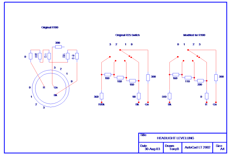
With respect to the wooden bezel it can be fitted to the later R100 with headlight adjustment. The original switch is removed, cut out etc, and one for a R45/R400 used. The resistors between the two switches have to be exchanged though. Schematic given below (click to enlarge)
If using the R400/R45 mirror switch then this can be fitted in the small panel to the right of the steering wheel using the R400/R45 bezel. R400/R45 mirror heater switch then easily slots in by the side of it. Metro Dash and Metro 100 GSi walnut trim panel cut ready for fitment of the R400/R45 dash bezel shown below:

Rover 400 switch bezel before fitment.
Dimensions for bracket to hold R400/R45 bezel in place
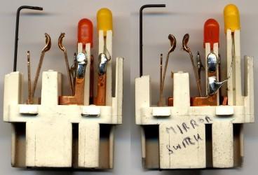
Metro Heated Rear Window Switch
The converted Metro HRW switch could go in the right hand side of the instrument assembly bezel under the rear fog lamp buttons. This avoids using a rocker switch which looks out of place..
Note the different colours for the wires in each connector:
The benefits of using a Metro switch to operate the heated mirror element is that the switch can be simply installed into a blank position the right hand side of the dash under the rear fog lamp switch. Thus avoiding any extra dash cutting if using original Rover adjustment switch and wanting switched heated elements. Note the modified position of the leads for the bulbs and one pin removed. Metro/100 H.R.W connector is colour keyed orange.
Rover 100 & Euro Metro Headlight level switch modifications (click to enlarge)
Guide Submitted by Tony Benton


